

Termination
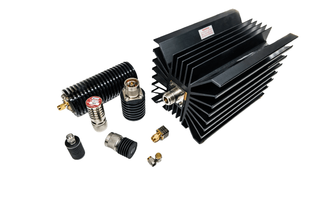
RF terminations, also called loads, are two-port devices calibrated to present a precise 50 ohm impedance and absorb incident power with minimal reflection. Every unused port in a multiport RF system needs a properly matched termination to prevent reflections from open ports from degrading measurement accuracy, increasing VSWR, or introducing interference into active signal paths. MCLI’s termination line covers standard coaxial models for bench and system use, as well as high power variants for transmitter test and dummy load applications.
Models are available in SMA and Type N connector configurations from DC to 18 GHz with VSWR as low as 1.30:1, with power handling ranging from 25 watts on standard coaxial models to high power designs for transmitter substitution and load testing. Download the MCLI catalog for the full model listing or request a quote for custom requirements.
MCLI ships terminations from St. Petersburg, Florida to defense, commercial, medical and research customers across the U.S. and worldwide.
Low VSWR, Low and High Power Solutions
High Reliability and Solid Build
Many Available Connector Configurations
Browse by category
Browse all Termination
Filters
Connector Series
Frequency Range (GHz)
Power Handling (W)
Showing all 81 results
| Part # | Connector | Frequency Range (GHz) | VSWR Max. | Power Handling (W) | Lead Time | Notes | Action |
|---|---|---|---|---|---|---|---|
| PCT-15-500/TF | TNC Female | DC – 2.4 | 1.20:1 | 500 | 8-9 Weeks | N/A | Request Quote |
| PCT-30-NF | N Female | DC – 2.4 | 1.10:1/ 1.35:1 | 30 | 8-9 Weeks | N/A | Request Quote |
| PCT-100-NF | N Female | DC – 2.4 | 1.10:1/ 1.35:1 | 100 | 8-9 Weeks | N/A | Request Quote |
| PCT-150-NF | N Female | DC – 2.4 | 1.10:1/ 1.35:1 | 150 | 8-9 Weeks | N/A | Request Quote |
| PCT-250-NF | N Female | DC – 2.4 | 1.10:1/ 1.35:1 | 250 | 8-9 Weeks | N/A | Request Quote |
| PCT-500-NF | N Female | DC – 2.4 | 1.25:1/1.20:1 | 500 | 8-9 Weeks | N/A | Request Quote |
| PCT-1000-716 | 7/16 Female | DC – 2.4 | 1.15:1/1.35:1 | 1000 | 8-9 Weeks | N/A | Request Quote |
| PCT-1000-NF | N Female | DC – 2.4 | 1.15:1/ 1.35:1 | 1000 | 8-9 Weeks | N/A | Request Quote |
| PCT-1500-NF | N Female | DC – 0.5 | 1.25:1 | 1500 | 8-9 Weeks | N/A | Request Quote |
| PCT-2000-NF | N Female | DC – 0.5 | 1.10:1 | 2000 | 8-9 Weeks | N/A | Request Quote |
| TNM-15-1000-SC | SC Male | DC - 2.4 | 1.35:1 | 1000 | 8-9 Weeks | N/A | Request Quote |
| T29M-40-5 | K Male | DC-40.0 | 1.35:1 | 5 | 8-9 Weeks | N/A | Request Quote |
| T35M-11-25 | 3.5mm Male | DC-26.5 | 1.25:1 | 25 | 8-9 Weeks | N/A | Request Quote |
| TSF-1 | SMA Female | DC-12.4 | 1.15:1 | 1 | 8-9 Weeks | N/A | Request Quote |
| TSF-2 | SMA Female | DC-18.0 | 1.20:1 | 1 | 8-9 Weeks | N/A | Request Quote |
| TSF-8 | SMA Female | DC-8.0 | 1.20:1 | 15 | 8-9 Weeks | N/A | Request Quote |
| TSF-9 | SMA Female | DC-12.0 | 1.25:1 | 15 | 8-9 Weeks | N/A | Request Quote |
| TSF-10 | SMA Female | DC-18.0 | 1.30:1 | 15 | 8-9 Weeks | N/A | Request Quote |
| TSF-17 | SMA Female | DC-6.0 | 1.25:1 | 50 | 8-9 Weeks | N/A | Request Quote |
| TSF-18 | 2.4mm Female | DC-50.0 | 1.45:1 | 1 | 8-9 Weeks | N/A | Request Quote |
| TSF-40 | K Female | DC-40.0 | 1.30:1 | 1 | 8-9 Weeks | N/A | Request Quote |
| TSM-1 | SMA Male | DC-18.0 | 1.25:1 | 1 | 8-9 Weeks | N/A | Request Quote |
| TSM-1X1 | SMA Male | DC-12.0 | 1.15:1 | 1 | 8-9 Weeks | N/A | Request Quote |
| TSM-1X2 | SMA Male | DC-12.0 | 1.15:1 | 1 | 8-9 Weeks | N/A | Request Quote |
| TSM-2 | SMA Male | DC-18.0 | 1.25:1 | 2 | 8-9 Weeks | N/A | Request Quote |
| TSM-2/CHN | SMA Male | DC-18.0 | 1.25:1 | 2 | 8-9 Weeks | N/A | Request Quote |
| TSM-3 | SMA Male | DC-12.0 | 1.25:1 | 2 | 8-9 Weeks | N/A | Request Quote |
| TSM-4 | SMA Male | DC-18.0 | 1.25:1 | 2 | 8-9 Weeks | N/A | Request Quote |
| TSM-5 | SMA Male | DC-8.0 | 1.20:1 | 5 | 8-9 Weeks | N/A | Request Quote |
| TSM-6 | SMA Male | DC-12.0 | 1.25:1 | 5 | 8-9 Weeks | N/A | Request Quote |
| TSM-7 | SMA Male | DC-18.0 | 1.30:1 | 5 | 8-9 Weeks | N/A | Request Quote |
| TSM-8 | SMA Male | DC-8.0 | 1.20:1 | 15 | 8-9 Weeks | N/A | Request Quote |
| TSM-9 | SMA Male | DC-12.0 | 1.25:1 | 15 | 8-9 Weeks | N/A | Request Quote |
| TSM-10 | SMA Male | DC-18.0 | 1.30:1 | 15 | 8-9 Weeks | N/A | Request Quote |
| TSM-10-50 | SMA Male | DC-2.0 | 1.10:1 | 50 | 8-9 Weeks | N/A | Request Quote |
| TSM-11 | SMA Male | DC-26.5 | 1.20:1 | 1 | 8-9 Weeks | N/A | Request Quote |
| TSM-17 | SMA Male | DC-6.0 | 1.25:1 | 50 | 8-9 Weeks | N/A | Request Quote |
| TSM-18 | 2.4mm Male | DC-50.0 | 1.45:1 | 1 | 8-9 Weeks | N/A | Request Quote |
| TSM-40 | K Male | DC-40.0 | 1.20:1 | 0.5 | 8-9 Weeks | N/A | Request Quote |
| TSM-40-1 | K Male | DC-40.0 | 1.25:1 | 1 | 8-9 Weeks | N/A | Request Quote |
| TBM-1-75 | BNC Male | DC-12.0 | 1.15:1 | 5 | 8-9 Weeks | N/A | Request Quote |
| TBF-1 | BNC Female | DC-12.0 | 1.15:1 | 5 | 8-9 Weeks | N/A | Request Quote |
| TBF-2 | BNC Female | DC-18.0 | 1.25:1 | 5 | 8-9 Weeks | N/A | Request Quote |
| TBM-1 | BNC Male | DC-12.0 | 1.15:1 | 5 | 8-9 Weeks | N/A | Request Quote |
| TBM-2 | BNC Male | DC-18.0 | 1.25:1 | 5 | 8-9 Weeks | N/A | Request Quote |
| TDM-3-50 | 7/16 Male | DC-3.0 | 1.20:1 | 50 | 8-9 Weeks | N/A | Request Quote |
| TDM-7-2 | 7/16 Male | DC-7.5 | 1.20:1 | 2 | 8-9 Weeks | N/A | Request Quote |
| TDM-7-5 | 7/16 Male | DC-7.5 | 1.20:1 | 5 | 8-9 Weeks | N/A | Request Quote |
| TTF-1 | TNC Female | DC-12.0 | 1.15:1 | 5 | 8-9 Weeks | N/A | Request Quote |
| TTF-2 | TNC Female | DC-18.0 | 1.25:1 | 5 | 8-9 Weeks | N/A | Request Quote |
| TTM-1 | TNC Male | DC-12.0 | 1.15:1 | 5 | 8-9 Weeks | N/A | Request Quote |
| TTM-2 | TNC Male | DC-18.0 | 1.35:1 | 5 | 8-9 Weeks | N/A | Request Quote |
| TTM-3 | TNC Male | DC-18.0 | 1.35:1 | 10 | 8-9 Weeks | N/A | Request Quote |
| TNF-1 | N Female | DC-12.0 | 1.15:1 | 5 | 8-9 Weeks | N/A | Request Quote |
| TNF-2 | N Female | DC-18.0 | 1.25:1 | 5 | 8-9 Weeks | N/A | Request Quote |
| TNF-15-500 | N Female | DC-2.4 | 1.35:1 | 50 | 8-9 Weeks | N/A | Request Quote |
| TNF-21 | N Female | DC-6.0 | 1.25:1 | 50 | 8-9 Weeks | N/A | Request Quote |
| TNF-50 | N Female | DC-18.0 | 1.45:1 | 50 | 8-9 Weeks | N/A | Request Quote |
| TNM-1 | N Male | DC-12.0 | 1.15:1 | 5 | 8-9 Weeks | N/A | Request Quote |
| TNM-1-50 | N Male | DC-12.0 | 1.15:1 | 5 | 8-9 Weeks | N/A | Request Quote |
| TNM-2 | N Male | DC-18.0 | 1.25:1 | 5 | 8-9 Weeks | N/A | Request Quote |
| TNM-3 | N Male | DC-4.0 | 1.15:1 | 10 | 8-9 Weeks | N/A | Request Quote |
| TNM-4 | N Male | DC-8.0 | 1.20:1 | 10 | 8-9 Weeks | N/A | Request Quote |
| TNM-5 | N Male | DC-12.0 | 1.25:1 | 10 | 8-9 Weeks | N/A | Request Quote |
| TNM-6 | N Male | DC-18.0 | 1.30:1 | 10 | 8-9 Weeks | N/A | Request Quote |
| TNM-7 | N Male | DC-4.0 | 1.15:1 | 15 | 8-9 Weeks | N/A | Request Quote |
| TNM-8 | N Male | DC-8.0 | 1.20:1 | 15 | 8-9 Weeks | N/A | Request Quote |
| TNM-9 | N Male | DC-12.0 | 1.30:1 | 15 | 8-9 Weeks | N/A | Request Quote |
| TNM-10 | N Male | DC-18.0 | 1.30:1 | 15 | 8-9 Weeks | N/A | Request Quote |
| TNM-11 | N Male | DC-4.0 | 1.15:1 | 25 | 8-9 Weeks | N/A | Request Quote |
| TNM-12 | N Male | DC-8.0 | 1.20:1 | 25 | 8-9 Weeks | N/A | Request Quote |
| TNM-13 | N Male | DC-12.0 | 1.30:1 | 25 | 8-9 Weeks | N/A | Request Quote |
| TNM-14 | N Male | DC-18.0 | 1.30:1 | 25 | 8-9 Weeks | N/A | Request Quote |
| TNM-15-25 | N Male | DC-6.0 | 1.20:1 | 25 | 8-9 Weeks | N/A | Request Quote |
| TNM-15-50 | N Male | DC-6.0 | 1.25:1 | 50 | 8-9 Weeks | N/A | Request Quote |
| TNM-15-150 | N Male | DC-2.4 | 1.35:1 | 150 | 8-9 Weeks | N/A | Request Quote |
| TNM-15-250 | N Male | DC-2.4 | 1.35:1 | 250 | 8-9 Weeks | N/A | Request Quote |
| TNM-21 | N Male | DC-6.0 | 1.25:1 | 50 | 8-9 Weeks | N/A | Request Quote |
| TNM-22-50 | N Male | DC-2.0 | 1.10:1 | 50 | 8-9 Weeks | N/A | Request Quote |
| TNM-50 | N Male | DC-18.0 | 1.45:1 | 50 | 8-9 Weeks | N/A | Request Quote |
| TNM-114 | N Male | DC-4.0 | 1.12:1 | 5 | 8-9 Weeks | N/A | Request Quote |
Full Product Line Specifications
| Parameter | Standard Coaxial | High Power |
|---|---|---|
| Frequency Range | DC to 18 GHz | Series-dependent |
| Impedance | 50 ohms | 50 ohms |
| VSWR | As low as 1.30:1 | Series-dependent |
| Power Handling | Up to 25 W | High power models available |
| Connector Options | SMA, Type N | Type N, other on request |
| Custom Options | Connector type, power level, frequency range | Power level, connector, mounting configuration |
Where MCLI Terminations Are Used
Unused Port Termination in Multiport Devices
Power dividers, directional couplers, hybrids, and circulators all have ports that may not be connected in a given system configuration. An open port on any of these devices presents a mismatched impedance at the junction, degrading port-to-port isolation and VSWR. A matched 50 ohm termination on each unused port ensures the device performs to its rated specifications.
Transmitter Dummy Load
Calibration and Measurement Reference
Frequently Asked Questions: Terminations
Why Does an Unused Port Need a Termination Instead of Being Left Open?
What Is the Difference Between a Termination and a Fixed Attenuator?
A termination is a one-port device designed to absorb all incident power at a single connector with no through path. A fixed attenuator is a two-port device that passes a signal from input to output with a defined, calibrated reduction in power. Use a termination to cap an unused port or substitute for a load. Use a fixed attenuator to reduce signal level in a through signal path.
What Is the Difference Between a Coaxial Termination and a Waveguide Termination?
A coaxial termination uses a resistive element inside a coaxial connector body to absorb RF energy in a 50 ohm coaxial transmission line. A waveguide termination uses an absorptive material or resistive wedge inside a waveguide housing to absorb electromagnetic energy propagating in the waveguide. The two are not interchangeable. Select the type that matches the transmission line interface in your system.
How Do I Select the Right Power Rating?
Size the termination’s power rating to handle the maximum continuous wave power present at the port under all operating conditions, including fault conditions where full transmitter power may be inadvertently routed to a normally low-power port. For pulsed transmitter applications, confirm both peak and average power handling ratings, as these are separate specifications. Contact MCLI for guidance on high power termination selection for your specific duty cycle and power level.