

Zero-Bias Diode Detectors
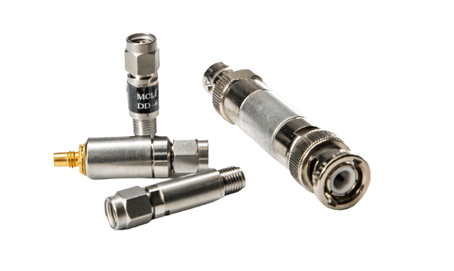
The line covers 10 MHz to 18.5 GHz with flatness of +/- 0.5 dB, low level sensitivity of 0.5 mV/uW, VSWR as low as 1.40:1, and a choice of positive or negative output polarity. SMA Male input connectors are standard, with BNC Female or SMA Female video output options depending on the model.
These detectors are designed, built and tested by MCLI’s RF and microwave engineers at our U.S. manufacturing plant, the same team that has supplied components to defense, commercial and research customers for over 40 years.
Positive and Negative Polarity Models
Broadband and Flat Frequency Solutions
High Reliability and Temperature Stability
Browse all Zero-Bias Diode Detectors
Showing all 18 results
| Part # | Frequency Range (GHz) | VSWR Max. | Flatness (±dB) | Low Level Sensitivity (mV/uW) | Input Connector | Output Connector | Lead Time | Notes | Action | |
|---|---|---|---|---|---|---|---|---|---|---|
| Min | Max | |||||||||
| ZD-7-X | 0.001 | 2 | 1.30:1 | 0.3 | 0.5 | BNC Male | BNC Female | 4-6 Weeks | Specify Positive or Negative Polarity when submitting. | Request Quote |
| ZD-8-X | 0.001 | 4 | 1.30:1 | 0.3 | 0.5 | BNC Male | BNC Female | 4-6 Weeks | Specify Positive or Negative Polarity when submitting. | Request Quote |
| ZD-1-X | 0.01 | 12.4 | 1.40:1 | 0.3 | 0.5 | SMA Male | SMA Female | 4-6 Weeks | Specify Positive or Negative Polarity when submitting. | Request Quote |
| ZD-2-X | 0.01 | 12.4 | 1.50:1 | 0.5 | 0.5 | SMA Male | SMA Female | 4-6 Weeks | Specify Positive or Negative Polarity when submitting. | Request Quote |
| ZD-3-X | 0.01 | 18.5 | 1.40:1 | 0.5 | 0.5 | SMA Male | SMA Female | 4-6 Weeks | Specify Positive or Negative Polarity when submitting. | Request Quote |
| ZD-4-X | 0.01 | 18.5 | 1.50:1 | 0.5 | 0.5 | SMA Male | SMC Male | 4-6 Weeks | Specify Positive or Negative Polarity when submitting. | Request Quote |
| ZD-5-X | 0.01 | 26.5 | 1.50:1 | 1 | 0.5 | SMA Male | SMA Female | 4-6 Weeks | Specify Positive or Negative Polarity when submitting. | Request Quote |
| ZD-6-X | 0.01 | 26.5 | 1.60:1 | 1 | 0.5 | SMA Male | SMC Male | 4-6 Weeks | Specify Positive or Negative Polarity when submitting. | Request Quote |
| ZD-9-X | 0.01 | 12.4 | 1.40:1 | 0.5 | 0.5 | SMA Male | BNC Female | 4-6 Weeks | Specify Positive or Negative Polarity when submitting. | Request Quote |
| ZD-10-X | 0.01 | 12.4 | 1.40:1 | 0.5 | 0.5 | N Male | BNC Female | 4-6 Weeks | Specify Positive or Negative Polarity when submitting. | Request Quote |
| ZD-11-X | 0.01 | 18.5 | 1.50:1 | 0.5 | 0.5 | SMA Male | BNC Female | 4-6 Weeks | Specify Positive or Negative Polarity when submitting. | Request Quote |
| ZD-12-X | 0.01 | 18.5 | 1.50:1 | 0.5 | 0.5 | N Male | BNC Female | 4-6 Weeks | Specify Positive or Negative Polarity when submitting. | Request Quote |
| ZD-14-X | 0.01 | 40 | 1.80:1 | 1 | 0.4 | K Male | SMA Female | 4-6 Weeks | Specify Positive or Negative Polarity when submitting. | Request Quote |
| ZD-15-X | 0.01 | 4 | 1.20:1 | 0.5 | 0.5 | SMA Male | SMA Female | 4-6 Weeks | Specify Positive or Negative Polarity when submitting. | Request Quote |
| ZD-16-X | 0.01 | 50 | 2.00:1 | 1 | 0.4 | 2.4mm Male | SMA Female | 4-6 Weeks | Specify Positive or Negative Polarity when submitting. | Request Quote |
| ZDI-12 | 0.01 | 12.4 | 1.25:1 | 0.3 | 0.5 | Pin | Pin | 4-6 Weeks | N/A | Request Quote |
| ZDI-18 | 0.01 | 18.5 | 1.25:1 | 0.5 | 0.5 | Pin | Pin | 4-6 Weeks | N/A | Request Quote |
| ZDI-26 | 0.01 | 26.5 | 1.25:1 | 1 | 0.5 | Pin | Pin | 4-6 Weeks | N/A | Request Quote |
Full Product Line Specifications
| Parameter | Value |
|---|---|
| Detector Type | Zero-bias Schottky diode |
| Frequency Range | 10 MHz (0.01 GHz) to 18.5 GHz |
| Flatness | +/- 0.5 dB |
| Low Level Sensitivity | 0.5 mV/uW |
| VSWR | 1.40:1 to 1.50:1 (model-dependent) |
| Input Connector | SMA Male |
| Output Connector | BNC Female (ZD-11) or SMA Female (ZD-3) |
| Output Polarity | Positive or negative; specify at time of order |
| DC Bias Required | None |
| Lead Time | 1 to 2 weeks |
Where MCLI Zero-Bias Diode Detectors Are Used
Transmitter Power Monitoring
Detectors placed at the coupled port of a directional coupler sample a small fraction of forward transmit power and convert it to a DC voltage for monitoring by a control circuit. Zero-bias detectors simplify this function by eliminating the need for a bias supply at the detector location, which is particularly useful in distributed antenna systems and remote transmitter installations where adding a DC supply at the detector point is impractical.
Receiver Signal Presence Detection
AGC and Leveling Feedback
Automatic gain control loops and leveling circuits require a detected voltage that tracks RF signal level to drive the control input of a variable attenuator or gain stage. Zero-bias detectors provide this feedback voltage across the full 10 MHz to 18.5 GHz operating range with +/- 0.5 dB flatness, keeping the detected voltage proportional to actual RF power across the band.
Frequently Asked Questions: Zero-Bias Diode Detectors
How Does a Zero-Bias Schottky Diode Detector Work Without DC Power?
A Schottky diode has a lower forward voltage threshold than a standard PN junction diode, low enough that moderate RF signal levels provide sufficient energy to forward bias the diode and produce rectified current without any externally applied bias voltage. The resulting DC current flows through a load resistor to produce the video output voltage.
At very low RF input power levels, the diode operates in the square law region where output voltage is proportional to input power. At higher power levels, it transitions to a linear detection region. Zero-bias operation is possible because Schottky diodes are specifically selected for low threshold voltage and high sensitivity.
What Does Output Polarity Mean and How Do I Select It?
What Is Low Level Sensitivity and How Does It Affect System Design?
Can the Detector Output Connect Directly to a Data Acquisition System?
Yes, provided the data acquisition system input impedance and voltage range are compatible with the detector’s output. The BNC Female output on the ZD-11 model is well suited for direct connection to oscilloscopes, power meters, and data acquisition systems using standard BNC cabling. The SMA Female output on the ZD-3 model suits integration into RF assembly housings where SMA connections are preferred throughout. Contact MCLI if your application requires a specific output impedance or voltage range not covered by the standard models.