

Every RF and microwave system that has to send one signal down different paths needs a clean way to route it. A coaxial switch does that job. It connects a common port to one of several output ports through a controlled signal path, so a single instrument can reach many devices, a radar can flip between transmit and receive, or a system can fall back to a spare amplifier when one fails. Pick the wrong switch and you pay for it in lost signal, poor isolation, or a part that wears out early.
This guide explains what a coaxial switch is, how electromechanical and solid state types differ, the specs that decide the choice, and how to match a switch to your application.
What Is a Coaxial Switch?
A coaxial switch routes an RF signal between transmission paths while holding the system’s characteristic impedance, usually 50 ohms. It has one common port and two or more output ports, each fitted with a coaxial connector such as SMA or Type N. Inside, it either moves a mechanical contact or biases a semiconductor to steer the signal to the selected port.
Engineers describe a switch by its poles and throws. SPDT means single pole, double throw: one input that connects to either of two outputs. An SP6T routes one input to any of six outputs. Transfer and multi-throw types extend that idea to more complex routing.
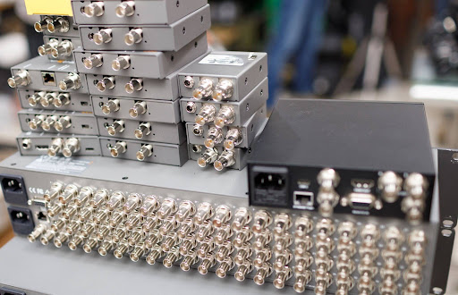
Test and measurement is the most common home for these parts. A switch matrix built from several units lets one analyzer test many devices without re-cabling, which is why RF electromechanical switches show up in nearly every automated test bench. They also route signals in radar, satellite, and instrumentation systems where a path has to change on command.
Electromechanical vs Solid State Coaxial Switches
Two technologies cover most of the market, and they trade off against each other in a predictable way.
An electromechanical switch uses a solenoid to move a metal contact that physically makes or breaks the path between ports. Because the signal travels through a metal-to-metal contact instead of a semiconductor junction, this type delivers low insertion loss, high isolation, and high power handling. The cost is switching speed, measured in milliseconds, and a finite number of mechanical cycles before the contacts wear.
A solid state switch steers the signal with a semiconductor element, usually a PIN diode or a FET, and has no moving parts. PIN diode switches and their FET cousins switch in microseconds and last far longer, but they carry more insertion loss and handle less power than an electromechanical switch at the same frequency.
The decision comes down to what your system values most. Choose electromechanical when signal integrity and power handling matter more than speed. Choose solid state when fast switching and high cycle counts outweigh the loss penalty.
Configurations: SPDT to SP6T and Transfer Switches
Coaxial switches come in several routing layouts, and the right one depends on how many paths your system addresses from a single port.
SPDT (single pole, double throw) is the workhorse: one input, two selectable outputs. Multi-throw types such as SP3T through SP6T connect one common port to three, four, five, or six outputs. A transfer switch, sometimes written DPDT, swaps two signal paths at the same time rather than routing one input to one output, which makes it the standard pick for redundancy and failover.
For more paths than a single switch can address, multiple units combine into a switch matrix. A common setup uses an SP6T to connect one analyzer to six devices under test in a rack. Each position presents the same impedance and insertion loss to the signal, so results stay consistent from port to port across a long test run.
The Specs That Decide the Choice
Once you know the technology and configuration, a handful of numbers tell you whether a specific part fits your system.
Insertion loss is the signal lost passing through the switch. Electromechanical coaxial switches often run 0.2 to 0.7 dB across their band. In test systems, the variation in that loss from one cycle to the next, called insertion loss repeatability, matters as much as the absolute figure, because it shows up as measurement error after calibration.
Isolation measures how well an off port blocks signal from reaching it. These switches reach 60 to 90 dB, which keeps crosstalk between paths from corrupting a measurement or a routed signal.
Switching speed separates the two technologies cleanly: milliseconds for electromechanical, microseconds for solid state. Match it to how often and how fast your system has to change paths.
Power handling favors electromechanical designs, which carry more power at a given frequency, derated as frequency climbs and conductor losses rise.
Hot switching and cold switching set the wear rate. Hot switching means actuating the switch while RF power is present on the ports. The energy crossing the contact as it opens or closes causes arcing that shortens contact life and degrades repeatability over time. Published IEEE research on hot-switching reliability documents how contact degradation tracks the energy dissipated at the contact during switching, which is why cold switching, where the RF is removed first, extends service life so much.
Cycle life follows from all of this. Electromechanical switches carry a rated number of operations, often in the millions of cold-switching cycles, while solid state switches have effectively unlimited switching life.
Latching, Failsafe, and Terminated vs Non-Terminated
Two more choices shape how a coaxial switch behaves in a live system.
Actuation mode controls what the switch does when power is removed. A failsafe switch returns to a default port whenever actuator power is lost, which gives the system a known signal path during a power interruption. A latching switch holds its last commanded position with no holding current, so it draws no power between changes, a good fit for low duty cycle or power-sensitive systems. A momentary switch holds its position only while energized.
Port termination decides what happens at the unused ports. A terminated switch loads each open port with an internal 50 ohm match, keeping the input impedance steady no matter which output is active and protecting sensitive sources from reflections. A non-terminated switch leaves unused ports open, which shaves a little insertion loss and works well when every port already connects to a matched load, as in most switch matrix builds.
Choosing and Specifying a Coaxial Switch
Start with four numbers: frequency range, the number of paths you need, power level, and how fast you have to switch. Those set the technology, electromechanical or solid state, and the configuration, from SPDT to a multi-throw or transfer layout.
Match the connector to the frequency. SMA and Type N cover most work below about 18 GHz, with Type N giving better power handling. Precision connectors such as 2.92mm, 2.4mm, and 1.85mm carry performance up into the millimeter-wave range above 18 GHz. Then pick the actuation mode by power and duty cycle, and decide terminated or non-terminated by whether unused ports see a matched load. Confirm both the cycle life and the hot-switching rating against how your system actually operates.
MCLI builds electromechanical coaxial switches from DC to 26.5 GHz in SPDT through SP6T, with failsafe, latching, and momentary actuation, terminated and non-terminated versions, power handling up to 200 W CW at 1.0 GHz, and a 28 Vdc actuator. For systems that need faster switching, MCLI also supplies PIN diode switches on the solid state side. If you are matching a switch to a test, radar, or redundancy application and want help specifying the right configuration, the MCLI engineering team can size the part to your requirements.
Frequently Asked Questions
What is a coaxial switch used for?
A coaxial switch routes one RF signal among several transmission paths without changing cables by hand. The most common use is automated test, where a switch matrix connects a single instrument to many devices under test. They also handle transmit and receive routing in radar, redundancy switching in satellite systems, and signal routing in instrumentation.
What is the difference between electromechanical and solid state coaxial switches?
An electromechanical switch moves a metal contact to make the path, giving low insertion loss, high isolation, and high power handling, but it switches in milliseconds and has a finite cycle life. A solid state switch uses a PIN diode or FET, so it switches in microseconds and lasts far longer, at the cost of higher insertion loss and lower power handling. Choose electromechanical for signal integrity and power, solid state for speed and cycle count.
What is hot switching, and why does it matter?
Hot switching means changing the signal path while RF power is still present on the ports. The energy crossing the contact as it opens or closes causes arcing and wear, which shortens contact life and degrades insertion loss repeatability over time. Cold switching, where the RF is removed before the switch moves, puts far less stress on the contacts and extends service life.
How long does a coaxial switch last?
Electromechanical coaxial switches are rated for a set number of operations, often in the millions of cold-switching cycles, with hot-switching life rated much lower. Solid state switches have no moving parts, so their switching life is effectively unlimited. The real figure depends on power level, switching frequency, and whether the system hot or cold switches.
What is a coaxial transfer switch?
A transfer switch, also called a DPDT switch, swaps two signal paths at once rather than routing one input to one output. It is widely used in redundancy setups, where a single command reroutes a system from a main path to a backup path. That makes it a common choice for failover between amplifiers or subsystems.
The Right Switch Is the One That Disappears
A coaxial switch should route your signal and then get out of the way. Get the technology right, electromechanical for low loss and power or solid state for speed, then pick the configuration and actuation mode your system needs and confirm the cycle and hot-switching ratings for your duty. Do that, and the switch holds its impedance, keeps its isolation, and repeats the same path reliably without becoming the weak link.